
Luoyang Yujie Industry&Trade Co., Ltd is one of the most experienced manufacturers and suppliers of wind turbine four point contact ball slewing bearing with teeth in China. Please feel free to buy cheap wind turbine four point contact ball slewing bearing with teeth for sale here from our factory. All customized products are with high quality and competitive price.
Product description:
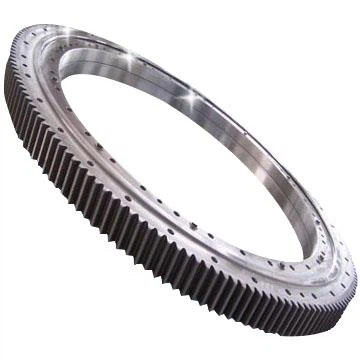
Yogie four point contact ball slewing bearing is made up of two seat rings. In this slewing bearing, the balls contact with the circular raceway at four points. The bearing can support axial force, radial force and resultant moment simultaneously,Yogie four point contact ball slewing ring bearing with high precision mainly used for Wind turbine.
A Wind Turbine Four Point Contact Ball Slewing Bearing with Teeth refers to a specific type of bearing used in wind turbine systems.A slewing bearing, also known as a slewing ring or turntable bearing, is a large bearing that enables rotational movement between two components. In the case of wind turbines, it allows the turbine blades to rotate and adjust their position to capture the maximum amount of wind energy.
The term "four point contact" refers to the design of the bearing, which typically consists of four points of contact between the inner and outer rings. This design provides stability and load-bearing capacity, allowing for the transmission of large axial, radial, and moment loads.
The "ball" in the name refers to the rolling elements within the bearing. Ball bearings consist of steel balls that roll between the inner and outer rings, reducing friction and facilitating smooth movement.
The "teeth" indicate that the outer ring of the slewing bearing is equipped with gear teeth. These teeth interact with a corresponding gear mechanism in the wind turbine, allowing for controlled rotation and positioning of the turbine blades.
Wind turbine slewing bearings with teeth play a crucial role in ensuring the efficient operation of wind turbines. They provide support, stability, and controlled movement, allowing the turbine to track wind direction and optimize energy capture.
Application:
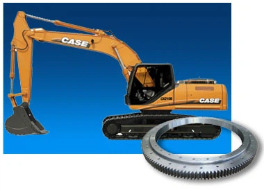
Our four point contact ball slewing bearings are compact in design and light in weight. They can be applied in Wind turbine,slewing conveyors, welding manipulators, middle or small sized cranes and excavators, etc.


| Designations | Boundary dimensions | Bolt hole diameter | Structure dimensions | Gear parameters | Basic load ratings | Mass | ||||||||||||||||
| D | d | H | D1 | D2 | n | φ | d1 | H1 | h | n3 | φ3 | m | Da | Z | da | Z | b | x | Coa | |||
| internal gear type | mm | mm | mm | mm | mm | mm | mm | mm | 104 N | kg | ||||||||||||
| 170 | 70 | 40 | 148 | 90 | 6 | 10 | 121 | 119 | 35 | 5 | 2 | M6x1 | 13 | 4.8 | ||||||||
| 240 | 90 | 36 | 214 | 116 | 8 | 10 | 179 | 177 | 28 | 8 | 2 | M6x1 | 20 | 9.24 | ||||||||
| 280 | 120 | 60 | 248 | 152 | 12 | 16 | 201 | 199 | 50 | 10 | 2 | M6x1 | 3 | 300 | 98 | 40 | 0 | 33 | 20 | |||
| 304 | 144 | 60 | 272 | 176 | 12 | 16 | 225 | 223 | 50 | 10 | 2 | M6x1 | 3 | 321 | 105 | 40 | 0 | 38 | 22 | |||
| 330 | 170 | 60 | 298 | 202 | 18 | 16 | 251 | 249 | 50 | 10 | 2 | M6x1 | 4 | 352 | 86 | 40 | 0 | 42 | 25 | |||
| 360 | 200 | 60 | 328 | 232 | 18 | 16 | 281 | 279 | 50 | 10 | 2 | M6x1 | 4 | 384 | 94 | 40 | 0 | 49 | 28 | |||
| 013.25.315 | 408 | 222 | 70 | 372 | 258 | 20 | 18 | 316 | 314 | 60 | 10 | 2 | M8x1 | 5 | 435 | 85 | 190 | 40 | 50 | 0 | 76 | 43 |
| 013.25.355 | 448 | 262 | 70 | 412 | 298 | 20 | 18 | 356 | 354 | 60 | 10 | 2 | M8x1 | 5 | 475 | 93 | 235 | 49 | 50 | 0 | 81 | 49 |
| 013.25.400 | 493 | 307 | 70 | 457 | 343 | 20 | 18 | 401 | 399 | 60 | 10 | 2 | M8x1 | 6 | 528 | 86 | 276 | 48 | 50 | 0 | 96 | 55 |
| 013.25.450 | 543 | 357 | 70 | 507 | 393 | 20 | 18 | 451 | 449 | 60 | 10 | 2 | M8x1 | 6 | 576 | 94 | 324 | 56 | 50 | 0 | 112 | 64 |
| 013·30·500·** | 602 | 398 | 80 | 566 | 434 | 20 | 18 | 498.5 | 501.5 | 70 | 10 | 4 | M10×1 | 5 | 630 | 123 | 365 | 74 | 60 | 0.5 | 129 | 75.8 |
| 014·30·500·** | 602 | 398 | 80 | 566 | 434 | 20 | 18 | 498.5 | 501.5 | 70 | 10 | 4 | M10×1 | 6 | 630 | 102 | 366 | 62 | 60 | 0.5 | 129 | 75.8 |
| 013·30·560·** | 662 | 458 | 80 | 626 | 494 | 20 | 18 | 558.5 | 561.5 | 70 | 10 | 4 | M10×1 | 5 | 690 | 135 | 425 | 86 | 60 | 0.5 | 144 | 94 |
| 014·30·560·** | 662 | 458 | 80 | 626 | 494 | 20 | 18 | 558.5 | 561.5 | 70 | 10 | 4 | M10×1 | 6 | 690 | 112 | 426.517 | 72 | 60 | 0.5 | 144 | 94 |
| 013·30·630·** | 732 | 528 | 80 | 696 | 564 | 24 | 18 | 628.5 | 631.5 | 70 | 10 | 4 | M10×1 | 6 | 774 | 126 | 492 | 83 | 60 | 0.5 | 187 | 110 |
| 014·30·630·** | 732 | 528 | 80 | 696 | 564 | 24 | 18 | 628.5 | 631.5 | 70 | 10 | 4 | M10×1 | 8 | 776 | 94 | 488 | 62 | 60 | 0.5 | 187 | 110 |
| 013·30·710·** | 812 | 608 | 80 | 776 | 644 | 24 | 18 | 708.5 | 711.5 | 70 | 10 | 4 | M10×1 | 6 | 852 | 139 | 570 | 86 | 60 | 0.5 | 212 | 120 |
| 014·30·710·** | 812 | 608 | 80 | 776 | 644 | 24 | 18 | 708.5 | 711.5 | 70 | 10 | 4 | M10×1 | 8 | 856 | 104 | 568 | 72 | 60 | 0.5 | 212 | 120 |
| 1098 | 893 | 90 | 1060 | 845 | 48/47 | 22 | 956.5 | 953.5 | 71 | 19 | 6 | M10×1 | 270 | 126 | ||||||||
| 013·40·800·12 | 922 | 678 | 100 | 878 | 722 | 30 | 22 | 798.5 | 801.5 | 90 | 10 | 6 | M10×1 | 8 | 968 | 118 | 632 | 80 | 80 | 0.5 | 313 | 256 |
| 014·40·800·** | 922 | 678 | 100 | 878 | 722 | 30 | 22 | 798.5 | 801.5 | 90 | 10 | 6 | M10×1 | 10 | 970 | 94 | 630 | 64 | 80 | 0.5 | 313 | 256 |
| 013·40·900·** | 1022 | 778 | 100 | 978 | 822 | 30 | 22 | 898.5 | 901.5 | 90 | 10 | 6 | M10×1 | 8 | 1064 | 130 | 736 | 93 | 80 | 0.5 | 355 | 240 |
| 014·40·900·** | 1022 | 778 | 100 | 978 | 822 | 30 | 22 | 898.5 | 901.5 | 90 | 10 | 6 | M10×1 | 10 | 1070 | 104 | 730 | 74 | 80 | 0.5 | 355 | 240 |
| 013·40·1000·** | 1122 | 878 | 100 | 1078 | 922 | 36 | 22 | 998.5 | 1001.5 | 90 | 10 | 6 | M10×1 | 10 | 1190 | 116 | 820 | 83 | 80 | 0.5 | 394 | 305 |
| 014·40·1000·** | 1122 | 878 | 100 | 1078 | 922 | 36 | 22 | 998.5 | 1001.5 | 90 | 10 | 6 | M10×1 | 12 | 1188 | 96 | 816 | 69 | 80 | 0.5 | 394 | 305 |
| 013·40·1120·** | 1242 | 998 | 100 | 1198 | 1042 | 36 | 22 | 1118 | 1122 | 90 | 10 | 6 | M10×1 | 10 | 1300 | 127 | 940 | 95 | 80 | 0.5 | 443 | 300 |
| 014·40·1120·** | 1242 | 998 | 100 | 1198 | 1042 | 36 | 22 | 1118 | 1122 | 90 | 10 | 6 | M10×1 | 12 | 1308 | 106 | 936 | 79 | 80 | 0.5 | 443 | 300 |
| 013·45·1250·** | 1390 | 1110 | 110 | 1337 | 1163 | 40 | 26 | 1248 | 1252 | 100 | 10 | 6 | M10×1 | 12 | 1452 | 118 | 1044 | 88 | 90 | 0.5 | 554 | 420 |
| 014·45·1250·** | 1390 | 1110 | 110 | 1337 | 1163 | 40 | 26 | 1248 | 1252 | 100 | 10 | 6 | M10×1 | 14 | 1456 | 101 | 1036 | 75 | 90 | 0.5 | 554 | 420 |
| 013·45·1400·** | 1540 | 1260 | 110 | 1487 | 1313 | 40 | 26 | 1398 | 1402 | 100 | 10 | 6 | M10×1 | 12 | 1608 | 131 | 1188 | 100 | 90 | 0.5 | 617 | 480 |
| 014·45·1400·** | 1540 | 1260 | 110 | 1487 | 1313 | 40 | 26 | 1398 | 1402 | 100 | 10 | 6 | M10×1 | 14 | 1610 | 112 | 1190 | 86 | 90 | 0.5 | 617 | 480 |
| 013·45·1600·** | 1740 | 1460 | 110 | 1687 | 1513 | 45 | 26 | 1598 | 1602 | 100 | 10 | 8 | M10×1 | 14 | 1820 | 127 | 1386 | 100 | 90 | 0.5 | 702 | 550 |
| 014·45·1600·** | 1740 | 1460 | 110 | 1687 | 1513 | 45 | 26 | 1598 | 1602 | 100 | 10 | 8 | M10×1 | 16 | 1824 | 111 | 1376 | 87 | 90 | 0.5 | 702 | 550 |
| 013·45·1800·** | 1940 | 1660 | 110 | 1887 | 1713 | 45 | 26 | 1798 | 1802 | 100 | 10 | 8 | M10×1 | 14 | 2016 | 141 | 1568 | 113 | 90 | 0.5 | 793 | 610 |
| 014·45·1800·** | 1940 | 1660 | 110 | 1887 | 1713 | 45 | 26 | 1798 | 1802 | 100 | 10 | 8 | M10×1 | 16 | 2016 | 123 | 1568 | 99 | 90 | 0.5 | 793 | 610 |
| 013·60·2000·** | 2178 | 1825 | 144 | 2110 | 1891 | 48 | 33 | 1998 | 2002 | 132 | 12 | 8 | M10×1 | 16 | 2272 | 139 | 1728 | 109 | 120 | 0.5 | 1210 | 1100 |
| 014·60·2000·** | 2178 | 1825 | 144 | 2110 | 1891 | 48 | 33 | 1998 | 2002 | 132 | 12 | 8 | M10×1 | 18 | 2268 | 123 | 1728 | 97 | 120 | 0.5 | 1210 | 1100 |
| 013·60·2240·** | 2418 | 2065 | 144 | 2350 | 2131 | 48 | 33 | 2237.5 | 2242.5 | 132 | 12 | 8 | M10×1 | 16 | 2496 | 153 | 1984 | 125 | 120 | 0.5 | 1350 | 1250 |
| 014·60·2240·** | 2418 | 2065 | 144 | 2350 | 2131 | 48 | 33 | 2237.5 | 2242.5 | 132 | 12 | 8 | M10×1 | 18 | 2502 | 136 | 1980 | 111 | 120 | 0.5 | 1350 | 1250 |
| 013·60·2500·** | 2678 | 2325 | 144 | 2610 | 2391 | 56 | 33 | 2497.5 | 2502.5 | 132 | 12 | 8 | M10×1 | 18 | 2772 | 151 | 2232 | 125 | 120 | 0.5 | 1500 | 1400 |
| 014·60·2500·** | 2678 | 2325 | 144 | 2610 | 2391 | 56 | 33 | 2497.5 | 2502.5 | 132 | 12 | 8 | M10×1 | 20 | 2780 | 136 | 2220 | 112 | 120 | 0.5 | 1500 | 1400 |
| 013·60·2800·** | 2978 | 2625 | 144 | 2910 | 2691 | 56 | 33 | 2797.5 | 2802.5 | 132 | 12 | 8 | M10×1 | 18 | 3078 | 168 | 2520 | 141 | 120 | 0.5 | 1680 | 1600 |
| 014·60·2800·** | 2978 | 2625 | 144 | 2910 | 2691 | 56 | 33 | 2797.5 | 2802.5 | 132 | 12 | 8 | M10×1 | 20 | 3080 | 151 | 2520 | 127 | 120 | 0.5 | 1680 | 1600 |
| 013·75·3150·** | 3376 | 2922 | 174 | 3286 | 3014 | 56 | 45 | 3147.5 | 3152.5 | 162 | 12 | 8 | M10×1 | 20 | 3480 | 171 | 2820 | 142 | 150 | 0.5 | 2380 | 2800 |
| 014·75·3150·** | 3376 | 2922 | 174 | 3286 | 3014 | 56 | 45 | 3147.5 | 3152.5 | 162 | 12 | 8 | M10×1 | 22 | 3476 | 115 | 2816 | 129 | 150 | 0.5 | 2380 | 2800 |
| 013·75·3550·** | 3776 | 3322 | 174 | 3686 | 3414 | 56 | 45 | 3547.5 | 3552.5 | 162 | 12 | 8 | M10×1 | 20 | 3880 | 191 | 3220 | 162 | 150 | 0.5 | 2690 | 3200 |
| 014·75·3550·** | 3776 | 3322 | 174 | 3686 | 3414 | 56 | 45 | 3547.5 | 3552.5 | 162 | 12 | 8 | M10×1 | 22 | 3894 | 174 | 3212 | 147 | 150 | 0.5 | 2690 | 3200 |
| 013·75·4000·** | 4226 | 3772 | 174 | 4136 | 3864 | 60 | 45 | 3997.5 | 4002.5 | 162 | 12 | 10 | M10×1 | 22 | 4334 | 194 | 3652 | 167 | 150 | 0.5 | 3020 | 3600 |
| 014·75·4000·** | 4226 | 3772 | 174 | 4136 | 3864 | 60 | 45 | 3997.5 | 4002.5 | 162 | 12 | 10 | M10×1 | 25 | 4350 | 171 | 3650 | 147 | 150 | 0.5 | 3020 | 3600 |
| 013·75·4500·** | 4726 | 4272 | 174 | 4636 | 4364 | 60 | 45 | 4497.5 | 4502.5 | 162 | 12 | 10 | M10×1 | 22 | 4840 | 271 | 4158 | 190 | 150 | 0.5 | 3410 | 4000 |
| 014·75·4500·** | 4726 | 4272 | 174 | 4636 | 4364 | 60 | 45 | 4497.5 | 4502.5 | 162 | 12 | 10 | M10×1 | 25 | 4850 | 191 | 4150 | 167 | 150 | 0.5 | 3410 | 4000 |

| Designation | Boundary dimensions | Bolt hole diameter | Structure dimensions | Gear parameters | Basic load ratings | Mass | ||||||||||||||||
| D | d | H | D1 | D2 | n | φ | D3 | d1 | H1 | h | n3 | φ3 | m | Da | Z | da | Z | b | x | Coa | ||
| external gear type | mm | mm | mm | mm | mm | mm | mm | mm | 104 N | kg | ||||||||||||
| 170 | 70 | 40 | 148 | 90 | 6 | 10 | 121 | 119 | 35 | 5 | 2 | M6x1 | 13 | 4.8 | ||||||||
| 240 | 90 | 36 | 214 | 116 | 8 | 10 | 179 | 177 | 28 | 8 | 2 | M6x1 | 20 | 9.24 | ||||||||
| 011.20.200 | 280 | 120 | 60 | 248 | 152 | 12 | 16 | 201 | 199 | 50 | 10 | 2 | M6x1 | 3 | 300 | 98 | 40 | 0 | 33 | 20 | ||
| 011.20.224 | 304 | 144 | 60 | 272 | 176 | 12 | 16 | 225 | 223 | 50 | 10 | 2 | M6x1 | 3 | 321 | 105 | 40 | 0 | 38 | 22 | ||
| 011.20.250 | 330 | 170 | 60 | 298 | 202 | 18 | 16 | 251 | 249 | 50 | 10 | 2 | M6x1 | 4 | 352 | 86 | 40 | 0 | 42 | 25 | ||
| 011.20.280 | 360 | 200 | 60 | 328 | 232 | 18 | 16 | 281 | 279 | 50 | 10 | 2 | M6x1 | 4 | 384 | 94 | 40 | 0 | 49 | 28 | ||
| 011.25.315 | 408 | 222 | 70 | 372 | 258 | 20 | 18 | 316 | 314 | 60 | 10 | 2 | M8x1 | 5 | 435 | 85 | 190 | 40 | 50 | 0 | 76 | 43 |
| 011.25.355 | 448 | 262 | 70 | 412 | 298 | 20 | 18 | 356 | 354 | 60 | 10 | 2 | M8x1 | 5 | 475 | 93 | 235 | 49 | 50 | 0 | 81 | 49 |
| 011.25.400 | 493 | 307 | 70 | 457 | 343 | 20 | 18 | 401 | 399 | 60 | 10 | 2 | M8x1 | 6 | 528 | 86 | 276 | 48 | 50 | 0 | 96 | 55 |
| 011.25.450 | 543 | 357 | 70 | 507 | 393 | 20 | 18 | 451 | 449 | 60 | 10 | 2 | M8x1 | 6 | 576 | 94 | 324 | 56 | 50 | 0 | 112 | 64 |
| 011·30·500·** | 602 | 398 | 80 | 566 | 434 | 20 | 18 | 498.5 | 501.5 | 70 | 10 | 4 | M10×1 | 5 | 630 | 123 | 365 | 74 | 60 | 0.5 | 129 | 75.8 |
| 012·30·500·** | 602 | 398 | 80 | 566 | 434 | 20 | 18 | 498.5 | 501.5 | 70 | 10 | 4 | M10×1 | 6 | 630 | 102 | 366 | 62 | 60 | 0.5 | 129 | 75.8 |
| 011·30·560·** | 662 | 458 | 80 | 626 | 494 | 20 | 18 | 558.5 | 561.5 | 70 | 10 | 4 | M10×1 | 5 | 690 | 135 | 425 | 86 | 60 | 0.5 | 144 | 94 |
| 012·30·560·** | 662 | 458 | 80 | 626 | 494 | 20 | 18 | 558.5 | 561.5 | 70 | 10 | 4 | M10×1 | 6 | 690 | 112 | 426.517 | 72 | 60 | 0.5 | 144 | 94 |
| 011·30·630·** | 732 | 528 | 80 | 696 | 564 | 24 | 18 | 628.5 | 631.5 | 70 | 10 | 4 | M10×1 | 6 | 774 | 126 | 492 | 83 | 60 | 0.5 | 187 | 110 |
| 012·30·630·** | 732 | 528 | 80 | 696 | 564 | 24 | 18 | 628.5 | 631.5 | 70 | 10 | 4 | M10×1 | 8 | 776 | 94 | 488 | 62 | 60 | 0.5 | 187 | 110 |
| 011·30·710·** | 812 | 608 | 80 | 776 | 644 | 24 | 18 | 708.5 | 711.5 | 70 | 10 | 4 | M10×1 | 6 | 852 | 139 | 570 | 86 | 60 | 0.5 | 212 | 120 |
| 012·30·710·** | 812 | 608 | 80 | 776 | 644 | 24 | 18 | 708.5 | 711.5 | 70 | 10 | 4 | M10×1 | 8 | 856 | 104 | 568 | 72 | 60 | 0.5 | 212 | 120 |
| 1098 | 893 | 90 | 1060 | 845 | 48/47 | 22 | 956.5 | 953.5 | 71 | 19 | 6 | M10×1 | 270 | 126 | ||||||||
| 011·40·800·** | 922 | 678 | 100 | 878 | 722 | 30 | 22 | 798.5 | 801.5 | 90 | 10 | 6 | M10×1 | 8 | 968 | 118 | 632 | 80 | 80 | 0.5 | 313 | 256 |
| 012·40·800·** | 922 | 678 | 100 | 878 | 722 | 30 | 22 | 798.5 | 801.5 | 90 | 10 | 6 | M10×1 | 10 | 970 | 94 | 630 | 64 | 80 | 0.5 | 313 | 256 |
| 011·40·900·** | 1022 | 778 | 100 | 978 | 822 | 30 | 22 | 898.5 | 901.5 | 90 | 10 | 6 | M10×1 | 8 | 1064 | 130 | 736 | 93 | 80 | 0.5 | 355 | 240 |
| 012·40·900·** | 1022 | 778 | 100 | 978 | 822 | 30 | 22 | 898.5 | 901.5 | 90 | 10 | 6 | M10×1 | 10 | 1070 | 104 | 730 | 74 | 80 | 0.5 | 355 | 240 |
| 011·40·1000·12 | 1122 | 878 | 100 | 1078 | 922 | 36 | 22 | 998.5 | 1001.5 | 90 | 10 | 6 | M10×1 | 10 | 1190 | 116 | 820 | 83 | 80 | 0.5 | 394 | 305 |
| 012·40·1000·** | 1122 | 878 | 100 | 1078 | 922 | 36 | 22 | 998.5 | 1001.5 | 90 | 10 | 6 | M10×1 | 12 | 1188 | 96 | 816 | 69 | 80 | 0.5 | 394 | 305 |
| 011·40·1120·** | 1242 | 998 | 100 | 1198 | 1042 | 36 | 22 | 1118 | 1122 | 90 | 10 | 6 | M10×1 | 10 | 1300 | 127 | 940 | 95 | 80 | 0.5 | 443 | 300 |
| 012·40·1120·** | 1242 | 998 | 100 | 1198 | 1042 | 36 | 22 | 1118 | 1122 | 90 | 10 | 6 | M10×1 | 12 | 1308 | 106 | 936 | 79 | 80 | 0.5 | 443 | 300 |
| 011·45·1250·** | 1390 | 1110 | 110 | 1337 | 1163 | 40 | 26 | 1248 | 1252 | 100 | 10 | 6 | M10×1 | 12 | 1452 | 118 | 1044 | 88 | 90 | 0.5 | 554 | 420 |
| 012·45·1250·** | 1390 | 1110 | 110 | 1337 | 1163 | 40 | 26 | 1248 | 1252 | 100 | 10 | 6 | M10×1 | 14 | 1456 | 101 | 1036 | 75 | 90 | 0.5 | 554 | 420 |
| 011·45·1400·** | 1540 | 1260 | 110 | 1487 | 1313 | 40 | 26 | 1398 | 1402 | 100 | 10 | 6 | M10×1 | 12 | 1608 | 131 | 1188 | 100 | 90 | 0.5 | 617 | 480 |
| 012·45·1400·** | 1540 | 1260 | 110 | 1487 | 1313 | 40 | 26 | 1398 | 1402 | 100 | 10 | 6 | M10×1 | 14 | 1610 | 112 | 1190 | 86 | 90 | 0.5 | 617 | 480 |
| 011·45·1600·** | 1740 | 1460 | 110 | 1687 | 1513 | 45 | 26 | 1598 | 1602 | 100 | 10 | 8 | M10×1 | 14 | 1820 | 127 | 1386 | 100 | 90 | 0.5 | 702 | 550 |
| 012·45·1600·** | 1740 | 1460 | 110 | 1687 | 1513 | 45 | 26 | 1598 | 1602 | 100 | 10 | 8 | M10×1 | 16 | 1824 | 111 | 1376 | 87 | 90 | 0.5 | 702 | 550 |
| 011·45·1800·** | 1940 | 1660 | 110 | 1887 | 1713 | 45 | 26 | 1798 | 1802 | 100 | 10 | 8 | M10×1 | 14 | 2016 | 141 | 1568 | 113 | 90 | 0.5 | 793 | 610 |
| 012·45·1800·** | 1940 | 1660 | 110 | 1887 | 1713 | 45 | 26 | 1798 | 1802 | 100 | 10 | 8 | M10×1 | 16 | 2016 | 123 | 1568 | 99 | 90 | 0.5 | 793 | 610 |
| 011·60·2000·** | 2178 | 1825 | 144 | 2110 | 1891 | 48 | 33 | 1998 | 2002 | 132 | 12 | 8 | M10×1 | 16 | 2272 | 139 | 1728 | 109 | 120 | 0.5 | 1210 | 1100 |
| 012·60·2000·** | 2178 | 1825 | 144 | 2110 | 1891 | 48 | 33 | 1998 | 2002 | 132 | 12 | 8 | M10×1 | 18 | 2268 | 123 | 1728 | 97 | 120 | 0.5 | 1210 | 1100 |
| 011·60·2240·** | 2418 | 2065 | 144 | 2350 | 2131 | 48 | 33 | 2237.5 | 2242.5 | 132 | 12 | 8 | M10×1 | 16 | 2496 | 153 | 1984 | 125 | 120 | 0.5 | 1350 | 1250 |
| 012·60·2240·** | 2418 | 2065 | 144 | 2350 | 2131 | 48 | 33 | 2237.5 | 2242.5 | 132 | 12 | 8 | M10×1 | 18 | 2502 | 136 | 1980 | 111 | 120 | 0.5 | 1350 | 1250 |
| 011·60·2500·** | 2678 | 2325 | 144 | 2610 | 2391 | 56 | 33 | 2497.5 | 2502.5 | 132 | 12 | 8 | M10×1 | 18 | 2772 | 151 | 2232 | 125 | 120 | 0.5 | 1500 | 1400 |
| 012·60·2500·** | 2678 | 2325 | 144 | 2610 | 2391 | 56 | 33 | 2497.5 | 2502.5 | 132 | 12 | 8 | M10×1 | 20 | 2780 | 136 | 2220 | 112 | 120 | 0.5 | 1500 | 1400 |
| 011·60·2800·** | 2978 | 2625 | 144 | 2910 | 2691 | 56 | 33 | 2797.5 | 2802.5 | 132 | 12 | 8 | M10×1 | 18 | 3078 | 168 | 2520 | 141 | 120 | 0.5 | 1680 | 1600 |
| 012·60·2800·** | 2978 | 2625 | 144 | 2910 | 2691 | 56 | 33 | 2797.5 | 2802.5 | 132 | 12 | 8 | M10×1 | 20 | 3080 | 151 | 2520 | 127 | 120 | 0.5 | 1680 | 1600 |
| 011·75·3150·** | 3376 | 2922 | 174 | 3286 | 3014 | 56 | 45 | 3147.5 | 3152.5 | 162 | 12 | 8 | M10×1 | 20 | 3480 | 171 | 2820 | 142 | 150 | 0.5 | 2380 | 2800 |
| 012·75·3150·** | 3376 | 2922 | 174 | 3286 | 3014 | 56 | 45 | 3147.5 | 3152.5 | 162 | 12 | 8 | M10×1 | 22 | 3476 | 115 | 2816 | 129 | 150 | 0.5 | 2380 | 2800 |
| 011·75·3550·** | 3776 | 3322 | 174 | 3686 | 3414 | 56 | 45 | 3547.5 | 3552.5 | 162 | 12 | 8 | M10×1 | 20 | 3880 | 191 | 3220 | 162 | 150 | 0.5 | 2690 | 3200 |
| 012·75·3550·** | 3776 | 3322 | 174 | 3686 | 3414 | 56 | 45 | 3547.5 | 3552.5 | 162 | 12 | 8 | M10×1 | 22 | 3894 | 174 | 3212 | 147 | 150 | 0.5 | 2690 | 3200 |
| 011·75·4000·** | 4226 | 3772 | 174 | 4136 | 3864 | 60 | 45 | 3997.5 | 4002.5 | 162 | 12 | 10 | M10×1 | 22 | 4334 | 194 | 3652 | 167 | 150 | 0.5 | 3020 | 3600 |
| 012·75·4000·** | 4226 | 3772 | 174 | 4136 | 3864 | 60 | 45 | 3997.5 | 4002.5 | 162 | 12 | 10 | M10×1 | 25 | 4350 | 171 | 3650 | 147 | 150 | 0.5 | 3020 | 3600 |
| 011·75·4500·** | 4726 | 4272 | 174 | 4636 | 4364 | 60 | 45 | 4497.5 | 4502.5 | 162 | 12 | 10 | M10×1 | 22 | 4840 | 271 | 4158 | 190 | 150 | 0.5 | 3410 | 4000 |
| 012·75·4500·** | 4726 | 4272 | 174 | 4636 | 4364 | 60 | 45 | 4497.5 | 4502.5 | 162 | 12 | 10 | M10×1 | 25 | 4850 | 191 | 4150 | 167 | 150 | 0.5 | 3410 | 4000 |

| Designations | Boundary dimensions | Bolt hole diameter | Structure dimensions | Gear parameters | Basic load ratings | Mass | ||||||||||||||||
| D | d | H | D1 | D2 | n | φ | D3 | d1 | H1 | h | n3 | φ3 | m | Da | Z | da | Z | b | x | Coa | ||
| non-gear type | mm | mm | mm | mm | mm | mm | mm | mm | 104 N | kg | ||||||||||||
| 010.12.120 | 170 | 70 | 40 | 148 | 90 | 6 | 10 | 121 | 119 | 35 | 5 | 2 | M6x1 | 13 | 4.8 | |||||||
| 010.13.178 | 240 | 90 | 36 | 214 | 116 | 8 | 10 | 179 | 177 | 28 | 8 | 2 | M6x1 | 20 | 9.24 | |||||||
| 010.20.200 | 280 | 120 | 60 | 248 | 152 | 12 | 16 | 201 | 199 | 50 | 10 | 2 | M6x1 | 3 | 300 | 98 | 40 | 0 | 33 | 20 | ||
| 010.20.224 | 304 | 144 | 60 | 272 | 176 | 12 | 16 | 225 | 223 | 50 | 10 | 2 | M6x1 | 3 | 321 | 105 | 40 | 0 | 38 | 22 | ||
| 010.20.250 | 330 | 170 | 60 | 298 | 202 | 18 | 16 | 251 | 249 | 50 | 10 | 2 | M6x1 | 4 | 352 | 86 | 40 | 0 | 42 | 25 | ||
| 010.20.280 | 360 | 200 | 60 | 328 | 232 | 18 | 16 | 281 | 279 | 50 | 10 | 2 | M6x1 | 4 | 384 | 94 | 40 | 0 | 49 | 28 | ||
| 010.25.315 | 408 | 222 | 70 | 372 | 258 | 20 | 18 | 316 | 314 | 60 | 10 | 2 | M8x1 | 5 | 435 | 85 | 190 | 40 | 50 | 0 | 76 | 43 |
| 010.25.355 | 448 | 262 | 70 | 412 | 298 | 20 | 18 | 356 | 354 | 60 | 10 | 2 | M8x1 | 5 | 475 | 93 | 235 | 49 | 50 | 0 | 81 | 49 |
| 010.25.400 | 493 | 307 | 70 | 457 | 343 | 20 | 18 | 401 | 399 | 60 | 10 | 2 | M8x1 | 6 | 528 | 86 | 276 | 48 | 50 | 0 | 96 | 55 |
| 010.25.450 | 543 | 357 | 70 | 507 | 393 | 20 | 18 | 451 | 449 | 60 | 10 | 2 | M8x1 | 6 | 576 | 94 | 324 | 56 | 50 | 0 | 112 | 64 |
| 010·30·500·12 | 602 | 398 | 80 | 566 | 434 | 20 | 18 | 498.5 | 501.5 | 70 | 10 | 4 | M10×1 | 5 | 630 | 123 | 365 | 74 | 60 | 0.5 | 129 | 75.8 |
| 602 | 398 | 80 | 566 | 434 | 20 | 18 | 498.5 | 501.5 | 70 | 10 | 4 | M10×1 | 6 | 630 | 102 | 366 | 62 | 60 | 0.5 | 129 | 75.8 | |
| 010·30·560·** | 662 | 458 | 80 | 626 | 494 | 20 | 18 | 558.5 | 561.5 | 70 | 10 | 4 | M10×1 | 5 | 690 | 135 | 425 | 86 | 60 | 0.5 | 144 | 94 |
| 662 | 458 | 80 | 626 | 494 | 20 | 18 | 558.5 | 561.5 | 70 | 10 | 4 | M10×1 | 6 | 690 | 112 | 426.517 | 72 | 60 | 0.5 | 144 | 94 | |
| 010·30·630·** | 732 | 528 | 80 | 696 | 564 | 24 | 18 | 628.5 | 631.5 | 70 | 10 | 4 | M10×1 | 6 | 774 | 126 | 492 | 83 | 60 | 0.5 | 187 | 110 |
| 732 | 528 | 80 | 696 | 564 | 24 | 18 | 628.5 | 631.5 | 70 | 10 | 4 | M10×1 | 8 | 776 | 94 | 488 | 62 | 60 | 0.5 | 187 | 110 | |
| 010·30·710·** | 812 | 608 | 80 | 776 | 644 | 24 | 18 | 708.5 | 711.5 | 70 | 10 | 4 | M10×1 | 6 | 852 | 139 | 570 | 86 | 60 | 0.5 | 212 | 120 |
| 812 | 608 | 80 | 776 | 644 | 24 | 18 | 708.5 | 711.5 | 70 | 10 | 4 | M10×1 | 8 | 856 | 104 | 568 | 72 | 60 | 0.5 | 212 | 120 | |
| 010·30·955·11 | 1098 | 893 | 90 | 1060 | 845 | 48/47 | 22 | 956.5 | 953.5 | 71 | 19 | 6 | M10×1 | 270 | 126 | |||||||
| 010·40·800·** | 922 | 678 | 100 | 878 | 722 | 30 | 22 | 798.5 | 801.5 | 90 | 10 | 6 | M10×1 | 8 | 968 | 118 | 632 | 80 | 80 | 0.5 | 313 | 256 |
| 922 | 678 | 100 | 878 | 722 | 30 | 22 | 798.5 | 801.5 | 90 | 10 | 6 | M10×1 | 10 | 970 | 94 | 630 | 64 | 80 | 0.5 | 313 | 256 | |
| 010·40·900·** | 1022 | 778 | 100 | 978 | 822 | 30 | 22 | 898.5 | 901.5 | 90 | 10 | 6 | M10×1 | 8 | 1064 | 130 | 736 | 93 | 80 | 0.5 | 355 | 240 |
| 1022 | 778 | 100 | 978 | 822 | 30 | 22 | 898.5 | 901.5 | 90 | 10 | 6 | M10×1 | 10 | 1070 | 104 | 730 | 74 | 80 | 0.5 | 355 | 240 | |
| 010·40·1000·** | 1122 | 878 | 100 | 1078 | 922 | 36 | 22 | 998.5 | 1001.5 | 90 | 10 | 6 | M10×1 | 10 | 1190 | 116 | 820 | 83 | 80 | 0.5 | 394 | 305 |
| 1122 | 878 | 100 | 1078 | 922 | 36 | 22 | 998.5 | 1001.5 | 90 | 10 | 6 | M10×1 | 12 | 1188 | 96 | 816 | 69 | 80 | 0.5 | 394 | 305 | |
| 010·40·1120·** | 1242 | 998 | 100 | 1198 | 1042 | 36 | 22 | 1118 | 1122 | 90 | 10 | 6 | M10×1 | 10 | 1300 | 127 | 940 | 95 | 80 | 0.5 | 443 | 300 |
| 1242 | 998 | 100 | 1198 | 1042 | 36 | 22 | 1118 | 1122 | 90 | 10 | 6 | M10×1 | 12 | 1308 | 106 | 936 | 79 | 80 | 0.5 | 443 | 300 | |
| 010·45·1250·** | 1390 | 1110 | 110 | 1337 | 1163 | 40 | 26 | 1248 | 1252 | 100 | 10 | 6 | M10×1 | 12 | 1452 | 118 | 1044 | 88 | 90 | 0.5 | 554 | 420 |
| 1390 | 1110 | 110 | 1337 | 1163 | 40 | 26 | 1248 | 1252 | 100 | 10 | 6 | M10×1 | 14 | 1456 | 101 | 1036 | 75 | 90 | 0.5 | 554 | 420 | |
| 010·45·1400·** | 1540 | 1260 | 110 | 1487 | 1313 | 40 | 26 | 1398 | 1402 | 100 | 10 | 6 | M10×1 | 12 | 1608 | 131 | 1188 | 100 | 90 | 0.5 | 617 | 480 |
| 1540 | 1260 | 110 | 1487 | 1313 | 40 | 26 | 1398 | 1402 | 100 | 10 | 6 | M10×1 | 14 | 1610 | 112 | 1190 | 86 | 90 | 0.5 | 617 | 480 | |
| 010·45·1600·** | 1740 | 1460 | 110 | 1687 | 1513 | 45 | 26 | 1598 | 1602 | 100 | 10 | 8 | M10×1 | 14 | 1820 | 127 | 1386 | 100 | 90 | 0.5 | 702 | 550 |
| 1740 | 1460 | 110 | 1687 | 1513 | 45 | 26 | 1598 | 1602 | 100 | 10 | 8 | M10×1 | 16 | 1824 | 111 | 1376 | 87 | 90 | 0.5 | 702 | 550 | |
| 010·45·1800·** | 1940 | 1660 | 110 | 1887 | 1713 | 45 | 26 | 1798 | 1802 | 100 | 10 | 8 | M10×1 | 14 | 2016 | 141 | 1568 | 113 | 90 | 0.5 | 793 | 610 |
| 1940 | 1660 | 110 | 1887 | 1713 | 45 | 26 | 1798 | 1802 | 100 | 10 | 8 | M10×1 | 16 | 2016 | 123 | 1568 | 99 | 90 | 0.5 | 793 | 610 | |
| 010·60·2000·** | 2178 | 1825 | 144 | 2110 | 1891 | 48 | 33 | 1998 | 2002 | 132 | 12 | 8 | M10×1 | 16 | 2272 | 139 | 1728 | 109 | 120 | 0.5 | 1210 | 1100 |
| 2178 | 1825 | 144 | 2110 | 1891 | 48 | 33 | 1998 | 2002 | 132 | 12 | 8 | M10×1 | 18 | 2268 | 123 | 1728 | 97 | 120 | 0.5 | 1210 | 1100 | |
| 010·60·2240·** | 2418 | 2065 | 144 | 2350 | 2131 | 48 | 33 | 2237.5 | 2242.5 | 132 | 12 | 8 | M10×1 | 16 | 2496 | 153 | 1984 | 125 | 120 | 0.5 | 1350 | 1250 |
| 2418 | 2065 | 144 | 2350 | 2131 | 48 | 33 | 2237.5 | 2242.5 | 132 | 12 | 8 | M10×1 | 18 | 2502 | 136 | 1980 | 111 | 120 | 0.5 | 1350 | 1250 | |
| 010·60·2500·** | 2678 | 2325 | 144 | 2610 | 2391 | 56 | 33 | 2497.5 | 2502.5 | 132 | 12 | 8 | M10×1 | 18 | 2772 | 151 | 2232 | 125 | 120 | 0.5 | 1500 | 1400 |
| 2678 | 2325 | 144 | 2610 | 2391 | 56 | 33 | 2497.5 | 2502.5 | 132 | 12 | 8 | M10×1 | 20 | 2780 | 136 | 2220 | 112 | 120 | 0.5 | 1500 | 1400 | |
| 010·60·2800·** | 2978 | 2625 | 144 | 2910 | 2691 | 56 | 33 | 2797.5 | 2802.5 | 132 | 12 | 8 | M10×1 | 18 | 3078 | 168 | 2520 | 141 | 120 | 0.5 | 1680 | 1600 |
| 2978 | 2625 | 144 | 2910 | 2691 | 56 | 33 | 2797.5 | 2802.5 | 132 | 12 | 8 | M10×1 | 20 | 3080 | 151 | 2520 | 127 | 120 | 0.5 | 1680 | 1600 | |
| 010·75·3150·** | 3376 | 2922 | 174 | 3286 | 3014 | 56 | 45 | 3147.5 | 3152.5 | 162 | 12 | 8 | M10×1 | 20 | 3480 | 171 | 2820 | 142 | 150 | 0.5 | 2380 | 2800 |
| 3376 | 2922 | 174 | 3286 | 3014 | 56 | 45 | 3147.5 | 3152.5 | 162 | 12 | 8 | M10×1 | 22 | 3476 | 115 | 2816 | 129 | 150 | 0.5 | 2380 | 2800 | |
| 010·75·3550·** | 3776 | 3322 | 174 | 3686 | 3414 | 56 | 45 | 3547.5 | 3552.5 | 162 | 12 | 8 | M10×1 | 20 | 3880 | 191 | 3220 | 162 | 150 | 0.5 | 2690 | 3200 |
| 3776 | 3322 | 174 | 3686 | 3414 | 56 | 45 | 3547.5 | 3552.5 | 162 | 12 | 8 | M10×1 | 22 | 3894 | 174 | 3212 | 147 | 150 | 0.5 | 2690 | 3200 | |
| 010·75·4000·** | 4226 | 3772 | 174 | 4136 | 3864 | 60 | 45 | 3997.5 | 4002.5 | 162 | 12 | 10 | M10×1 | 22 | 4334 | 194 | 3652 | 167 | 150 | 0.5 | 3020 | 3600 |
| 4226 | 3772 | 174 | 4136 | 3864 | 60 | 45 | 3997.5 | 4002.5 | 162 | 12 | 10 | M10×1 | 25 | 4350 | 171 | 3650 | 147 | 150 | 0.5 | 3020 | 3600 | |
| 010·75·4500·** | 4726 | 4272 | 174 | 4636 | 4364 | 60 | 45 | 4497.5 | 4502.5 | 162 | 12 | 10 | M10×1 | 22 | 4840 | 271 | 4158 | 190 | 150 | 0.5 | 3410 | 4000 |
| 4726 | 4272 | 174 | 4636 | 4364 | 60 | 45 | 4497.5 | 4502.5 | 162 | 12 | 10 | M10×1 | 25 | 4850 | 191 | 4150 | 167 | 150 | 0.5 | 3410 | 4000 | |
FAQ:
Q: Are you factory or trading company?
A:We are factory.
Q:Where are your factory located?
A:Our factory located in Jianxi Industrial park,Luoyang city,Henan province,China.
Q:Are crossed roller bearings your main products?
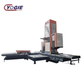
A:Yes,we have advanced equipments to produce crossed roller bearings,Vertical CNC lathe,CNC Grinding machine,Vertical CNC machining center VMC650 two axes linear rail for drilling,and other inspection machines.
Q:Whether your factory have large stock for this kind of bearings ?
A:Yes, we have a large stock of our products.Even if the product quantity is insufficient, we can produce it in the shortest time, because we have the most professional machinery and team.
Hot Tags: Wind Turbine Four Point Contact Ball Slewing Bearing with Teeth, manufacturers, supplier, factory, customized, cheap, price, in stock, for sale, cross roller slewing bearing, double row different diameter ball slewing bearing, Light load slewing bearing, rotary bearings, Slewing Bearing