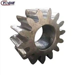
Classification and application of bevel gears
Bevel gears are also conical gears. The bevel gear is most commonly used as a transmission for two vertical shafts, but it is also suitable for two-axis transmission at other angles. The most typical application is to drive a vertical pump with a horizontal drive. The two main differences between bevel gears and spur gears are the relationship between their shape and the axis on which they are located. The bevel gear is conical in shape, while the spur gear is originally a cylinder. The bevel gear transmits motion between two angled shafts, that is, the intersecting shafts, while the spur gear transmits motion between two parallel shafts.
Characteristics of bevel gears
The bevel gear is mainly used to realize the transmission of motion and power between the two intersecting shafts. The intersection angle Σ of the two shafts is called the shaft angle. The value of Σ can be determined according to the needs of the transmission. Usually 90 degrees are used, that is, vertical intersection. The gear teeth of the bevel gear are arranged on a truncated cone. Therefore, the expressions corresponding to the "cylinders" in the cylindrical gears become "cones", such as indexing cones, pitch cones, base cones, addendum cones, etc. ; This is also the origin of the name of the bevel gear.
As can be seen from Figure 1, when a pair of standard straight bevel gears are driven, the indexing cones of the two wheels coincide with their respective pitch cones. The thickness of the gear tooth is large at one end and small at the other end, that is, the thickness of the gear tooth in the width direction of the gear is not the same, so the modulus, tooth height, and width of the tooth profile are different over the entire length of the gear tooth. Therefore, the model of the bevel gear tooth profile cannot be created by the simple stretching method of the standard cylindrical spur gear.
Classification and scope of application
There are several types of bevel gears:
(1) Straight bevel gear. This is the standard form of a bevel gear. Its tooth profile is perpendicular to the generatrix of the cone. The tooth height is in the form of shrinking teeth, that is, from the large end (outer end) of the tooth to the small end (inner end) of the indexing cone generatrix. The tooth height gradually decreases. The advantages of the straight tooth bevel gear are that the design, manufacture and installation are relatively simple and easy to adjust; the disadvantage is that the running noise is large and there is impact; it is suitable for low-speed transmission (<5m / s) occasions.
(2) Helical bevel gear. Similar to the formation of the tooth surface of a cylindrical spiral gear, the intersection of the involute spiral surface of the helical bevel gear and the base conical surface and any conical surface coaxial with the base conical surface is a conical spiral. The projection curve of a straight line with a β angle on the tangent plane of the indexing cone surface to the indexing cone generating line on the indexing cone surface (that is, the indexing cone spiral line) is usually used as a design reference to construct the Toothed. The tooth height of the helical bevel gear is also in the form of shrinking teeth. When a pair of helical bevel gears are engaged, like the helical cylindrical gears, the contact line of the tooth surface is a slant curve. The contact curve changes from short to long, then from long to short, until it is out of mesh. Therefore, compared with straight tooth bevel gears, helical bevel gears have smoother transmission, less impact and vibration, and are suitable for medium, high speed and heavy loads.
(3) Curved tooth bevel gear. Curved teeth are divided into arc teeth, long outer cycloidal teeth (cycloidal teeth for short) and quasi-involute teeth. Among them, the height of the cycloid bevel gear is in the form of constant height teeth, and the tooth height at each point along the dividing cone generatrix is unchanged, while the tooth height of the spiral bevel gear is still in the form of shrinking teeth. Curved tooth bevel gears have the characteristics of stable transmission, low noise and large carrying capacity. They are suitable for various types of mechanical equipment and vehicles (such as automobile differentials) with high speed and heavy load.
Processing of bevel gears
The bevel gear is processed on a special gear shaper. Bevel gears can also be processed on a universal milling machine, but the size and shape of the teeth are not precise. The bevel gear is often processed by a joint method, that is, the initial processing is performed on a universal milling machine or a horizontal milling machine. As for the finishing, that is, the calibration of the tooth shape, it is performed on a special machine tool for processing bevel gears.
Figure 2 is an illustration of the process of milling a bevel gear on a milling machine. The manufacturing process of the bevel gear consists of the following steps. The processed blank is placed on the mandrel, and the mandrel is fastened on the indexing head. The axis of the indexing pivot is turned to an angle equal to half the cone angle of the blank.
After the blank is installed, use a disk module cutter to mill the tooth groove to the full depth; at the same time, the cutter should match the module of the small radius of the gear being milled. All gear teeth are milled in this way. As for indexing, use the indexing head in the usual way.
Main features and functions
There are many mechanical transmission methods used on various machines, the most important ones are belt transmission, chain transmission, friction wheel transmission, gear transmission and ribbon nut transmission.
Among them, gear transmission generally means that one shaft can drive another shaft to rotate when it rotates; or it can change the rotary motion of one shaft to linear motion.
Its main characteristics are: the teeth are tightly meshed with each other, and the torque transmitted is much larger than that of belt and chain transmission; its transmission efficiency is also higher than that of other mechanical transmissions; Keep the speed ratio between the two shafts unchanged.
There are many types of gears, generally divided into cylindrical gears, conical gears and worm gears according to the shape of the tooth surface. Commonly used spur gears and helical gears are cylindrical gears, which are used to drive the rotation movement of two mutually parallel shafts, and the bevel gear (conical gear) is used to drive the rotation movement of the intersecting two shafts. When the teeth of a pair of bevel gears mesh with the transmission, the situation is very similar to the transmission of two semi-conical friction wheels, as shown in Figure 3. However, if the driven force of the driven shaft is greater than the friction between the two wheels in the transmission of the friction wheel, the two wheels will slip, or even a driven wheel cannot be driven. If the friction wheel is made into a toothed wheel, and the power of the tooth on the gear is used to drive the tooth on the other shaft, the rotating force of this shaft can be transmitted to the other shaft, as shown in Figure 4. The meshing transmission of the bevel gear is based on this.
The bevel gear has a wide range of uses. Especially when the two shafts intersect, the distance between the two shafts is very close, the transmission power is large, and the rotation ratio is fixed, the bevel gear is most suitable.