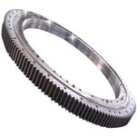
The history of helical gear and its applications
A helical gear's teeth are placed at an angle (relative to the gear's axis) and take the shape of a helix. This permits the teeth to progressively mesh, first with point contact and progressing to line contact as engagement develops. Less noise is one of the most obvious advantages of helical gears over spur gears, especially at medium- to high-speeds. Furthermore, with helical gears, several teeth are always in mesh, resulting in reduced strain on each individual tooth. This causes a smoother transfer of forces from one tooth to the next, reducing vibrations, shock loads, and wear.
") However, the inclined angle of the teeth generates sliding contact between the teeth, resulting in axial forces and heat, reducing efficiency. These axial forces are important in bearing choosing for helical gears. Helical gears require thrust or roller bearings, which are generally bigger (and more expensive) than the basic bearings used with spur gears since they must endure both radial and axial forces. The size of the tangent of the helix angle affects the axial forces. Despite the fact that bigger helix angles enable faster and smoother motion, the helix angle is generally limited to 45 degrees owing to the generation of axial forces.
However, the inclined angle of the teeth generates sliding contact between the teeth, resulting in axial forces and heat, reducing efficiency. These axial forces are important in bearing choosing for helical gears. Helical gears require thrust or roller bearings, which are generally bigger (and more expensive) than the basic bearings used with spur gears since they must endure both radial and axial forces. The size of the tangent of the helix angle affects the axial forces. Despite the fact that bigger helix angles enable faster and smoother motion, the helix angle is generally limited to 45 degrees owing to the generation of axial forces.
Helical gears' axial stresses can be mitigated by employing twin helical or herringbone gears. These configurations appear to be two helical gears with opposing hands placed back-to-back, but they are really machined from the same gear. (The difference between the two types is that double helical gears contain a groove between the teeth in the centre, whereas herringbone gears do not.) Because the axial pressures on each pair of teeth are cancelled out by this design, greater helix angles may be utilized. It also does away with the requirement for thrust bearings.
Aside from smoother motion, better speed capabilities, and less noise, helical gears have the benefit of being able to be utilized with either parallel or non-parallel (crossing) shafts. Helical gears with parallel shafts require the same helix angle as helical gears with opposite hands (i.e. right-handed teeth vs. left-handed teeth).
 2")
When using crossed helical gears, they might be of the same or opposite hands. The total of the helix angles should match the angle between the shafts if the gears have the same hands. Crossed helical gears with perpendicular (i.e. 90 degree) shafts are the most typical example of this. Both gears have the same hand, and their helix angles add up to 90 degrees. The angle between the shafts should equal the difference between the helix angles in setups with opposing hands. Crossed helical gears provide for greater design freedom, but because the contact between teeth is closer to point contact than line contact, they have lesser force capacities than parallel shaft versions.
In cases where spur gears are suitable but the shafts are not parallel, helical gears are frequently the default choice. They are also utilized in situations requiring high speeds or loads. They usually provide smoother, quieter operation than spur gears, regardless of load or speed.
Do you have any specific questions about the design or manufacture of Helical gears or Herringbone gears? Contact Yogie! Our sales engineers will work with you from start to finish to ensure that your project is completed to your requirements.
Also, Yogie is a professional manufacturer for mining equipment, CNC Machine tools, and machinery parts for over 20years.